Ultra-Thin Grinding
Solutions
In recent years, the demand for ultra-thin die for use in mobile phones, stacked packages, and a myriad of other applications has been increasing. DISCO delivers complete ultra-thin grinding solutions that comprise four key elements: machine, grinding wheel, protective tape, and processing conditions.
Application Examples
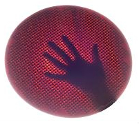
Photo 1 shows a Φ300 mm silicon wafer reduced to 5 µm thickness by grinding only. By optimizing the equipment, wheels, and grinding conditions introduced here, such thinness can be achieved using normal grinding only.
Equipment
The point of concern during ultra-thin grinding is how to safely handle the wafers, as their mechanical
strength is reduced making them extremely easy to crack due to the reduction in thickness.
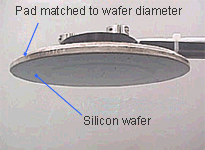
In addition to using transport pads (Photo 2) of the same diameter as the wafer, the transport system also
uses functions such as washing the pad surfaces to prevent particles becoming trapped between the wafer
and the pad. Further, as an effective method for solving wafer damage, the inline system (Photo 3) is also used
throughout, from grinding to DAF adhesion, wafer mounting, and removal of surface protection tape, without
major human interference.

(DGP8761 + DFM2800)
Wheels
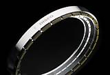
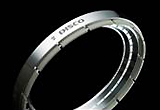
By changing from a vitrified bond (VS, VS202, etc), which has been used for rough grinding on Z1-axis, to
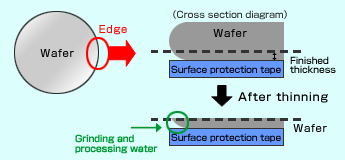
a resin bond BT100 (Photo 4), it is possible to lower damage and suppress edge chipping*1,
which is a cause of wafer breakage. Furthermore, by employing aZ2-axis wheel with BK-09 bond, which
supports a larger removal of Z1-axis grinding damage, it is possible to achieve thin grinding without a
stress relief process such as dry polishing (Photo 5).
Also, by using a BT100 wheel for rough grinding and a Poligrind (Photo 6), which uses
ultra-fine abrasive, for fine grinding, it has become possible to implement a thinning process, using
grinding only. This can be achieved not just for 8-inch wafers but also 300 mm wafers, which in many cases
would require a stress relief process. In addition to three-axis grinders, a Poligrind wheel can also be
employed on two-axis grinders for ultra-thin grinding by replacing the existing fine grinding wheel.

※1 The cross-section of the wafer edge area shows a rounded shape, but when thinning the wafer, this rounded edge takes on a sharp shape and mechanical strength is greatly weakened. Due to the influence of grinding water or process conditions, this edge area flutters and generates chipping that causes wafer breakage. (Fig. 1)
Grinding Conditions and Applications
(After Edge Trimming)
Grinding conditions enable low-load grinding for both coarse and fine grinding by decelerating the
feed speed of the grinding wheel spindle as the final finishing thickness is approached. Further,
applications such as accelerating at the wafer vacuum table while decelerating the spindle rotation
speed are effective as countermeasures to reduce edge chipping.
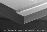
Edge trimming (Photo 7) is used as another solution to reduce edge chipping. This enables a wide edge
chipping reduction and is a process to prevent the edge shape from becoming sharp after the wafer
thickness has been reduced by cutting grooves into the wafer edge before starting the grinding
process.
-
the Wafer Edge
with edge trimming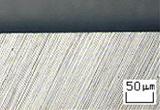
-
the Wafer Edge
without edge trimming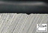
Improving Die Strength (Stress Relief)
The processing quality of ultra-thin finishing grinding can also be improved by using the Poligrind wheel, but a layer of powder (albeit slight) remains on the wafer surface due to processing using a grinding wheel. DISCO can supply various processes to meet customer needs regarding stress relief technology and which further improves the die strength by eliminating this powdered layer. (See Table 1.)
| Dry etching | This is a stress relief process that performs etching using fluorine-based plasma gas. Stress relief on the die edge is possible by combining with DBG*2. |
|---|---|
| Dry polishing | This is a dry stress relief process that uses dry polishing wheels. It does not use water or chemicals at all. |
Table 1: DISCO Stress Relief
*2 DBG (Dicing Before Grinding) is a technology that separates the die using backside grinding after first half-cutting the wafer. Backside chipping is also greatly reduced without the wafer warpage being affected.
Contact
Please feel free to contact us with any questions or inquiries.
-

Applications Support
A free-of-charge test cut is performed at an application lab to confirm whether achieving the customer's needs is possible.
Details -

Dicing and Grinding Service
It is effective in sample and prototype manufacturing during development or low-volume production. Designated engineers will provide support based on the desired leadtime and at reasonable cost.
Details
